
 Contact Us


Electrostatic Discharge
What is ESD?

ESD while only a slight annoyance to people, provides a challenge to electronics where the fast increase in voltage and current has the potential to cause severe damage. The picture on the right depicts how static charge is built up on a person and subsequently discharged on a computer. Electrostatic charge is most commonly created by the contact and separation of two materials.
The buildup of charge can occur from humans as well as machines or objects, which is commonly seen in industrial processes and manufacturing. The quick discharge of energy generates both voltage and current, which are used in defining (as well as other criteria) what constitutes an ESD event for immunity testing.
The video on the left describes electrostatic discharge including causes, commonly occurring voltage levels, and the impact it can have on PCBs.
ESD Testing
What is ESD Testing?
 ESD testing, part of electromagnetic compatibility (EMC), is focused on the impact that the operational environment can have on equipment under test (EUT). The goal of testing for ESD is to ensure immunity, or that performance or functionality of the equipment is not changed because of exposure to electrostatic discharge events.
This testing is done both at the component/device level or system level depending upon the device or equipment.
Application Guides & Handbooks
The bellow application notes, guides, and handbooks provide an excellent background on ESD as well as the most common requirements.
Contact & Air Discharge Methods
 The two most common methods for testing and EUT’s ability to withstand an ESD event are contact discharge and air discharge. Both methods are commonly referenced by a variety of standards with the contact discharge being often preferred.
Test levels for both methods are typically different, with air discharge commonly the largest for commercial applications at 16 kV. Different tips are used for both methods as shown on the left for the Teseq NSG 435 and Haefely ONYX16 ESD simulators.
Air Discharge
What is ESD air discharge method?

The air discharge method is commonly used for replicating real word events as well as when contact discharge is not possible. This more accurately simulates real world events as most discharges occur because of because of objects moving or separating.
This method requires an air discharge tip which is rounded to facilitate the arching across the air gap. These tips are commonly designed in accordance with IEC 61000-4-2 which places requirements on the design. There are many factors that have the potential to impact testing with the air discharge method they include:
Humidity - The lower the humidity the higher probability of a electrostatic discharge event occurring.
Temperature - The lower the temperature often leads to an increase in ESD events.
Speed of Approach - Attempt to duplicate the recommended speed ensuring compliance.
Contact Discharge
What is ESD contact discharge method?
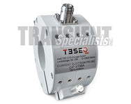
 The contact discharge method is the preferred method for a variety of ESD testing requirements including that of IEC 61000-4-2 given it helps to limit testing uncertainties. Although it is an ideal solution for more repeatable results, it does not as closely simulate how ESD events occur.
The associated image on the left shows the contact discharge tip on the EMC Partner ESD3000 simulator.
ESD Pulses & Test Levels

ESD pulses include both current and voltage components, with current waveform criteria (rise time, duration, etc.) verified for compliance to a particular standard.
The image on the left shows the correlation between different test levels and the associated voltages and current up to 8 kV or test level 4.
ESD Current Waveform

The current waveform for ESD testing is a major component in compliance to standards or test requirements. The most common of the commercial standards, IEC 61000-4-2, indicates a .8 ns rise time and current requirements at 60 ns and 30 ns for contact discharge.
The associated image on the right shows a pulse from the Teseq NSG 435, which is provided by the user manual. This example pulse indicates the common requirements for rise time as well as current requirements at different intervals. Each application or standard has the potential to have different pulse requirements making it crucial to verify capabilities prior to beginning testing.
What is the Time Between ESD Discharges?
ESD Voltage & Polarity

Voltage requirements for electrostatic discharge can vary both by discharge method and standard. It is common for ESD standards to have higher levels for air than contact discharge with automotive applications reaching 30 kV. Typically for commercial applications voltages will be limited to 16 kV air discharge and 8 kV contact discharge.
Testing both positive and negative polarity of pulses is required for compliance to most immunity standards. This is often done through selection on the menu screen on simulator, which includes many testing criteria including voltage and discharge method.
ESD Test Equipment
ESD Simulators/Guns
Electrostatic discharge simulators, or ESD guns, are primary based around the most common commercial pulse requirements of IEC 61000-4-2. These indicate test levels, waveform requirements, as well as design of the equipment. The video below provides an overview of a few of the most common ESD simulators.
The devices associated with replicating the associated voltage, current, and waveform requirements with an ESD event are referred to as ESD simulators or ESD guns.
There are a variety of different manufacturers, however typically simulators are broken down by max discharge voltage (~15kV-16kV & 30kV) as well as the resistance capacitance combination. The max values are typically relayed for air discharge given it has the highest voltage requirements.
Typically contact tips, resistance capacitance networks (also called RC networks) can be switched out to meet different testing criteria. The networks themselves can typically be purchased separately in a variety of common and custom combinations.
What is an ESD Simulator/Gun?
Air & Contact Discharge Tips

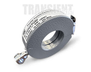
The majority of simulators today include both air and contact discharge tips with the simulator. The method by which they attach to the simulator is somewhat different for each unit, some slide on and some turn on. Regardless of how they are attached they are all required to be compliant to the associated test standard, typically IEC 61000-4-2.
The image on the right shows the Teseq NSG 435 ESD simulators contact and air discharge tips and how the attach to the simulator. There is also additional tips available allowing for modifications of risetime and testing methodology. These are typically used for special applications not typically required more common commercial requirements.
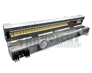
Resistance Capacitance (RC) Module/Network
The RC network is a combination of the resistance capacitance requirements, which are provided by the associated standard. For commercial applications this is commonly based around IEC 61000-4-2 which specifies 150 pF and 330 Ohms. These can very both by application and by test level, with some RC networks being custom made to meeting testing criteria.
ESD Voltage & Waveform Verification
The verification of both current waveform/pulse as well as voltage require a unique set of equipment, which is typically done on an annual basis. Some standards, as will MIL-STD-461 CS118 require verification of criteria prior to testing.
ESD Voltage/Test Level
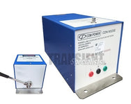
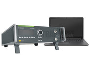
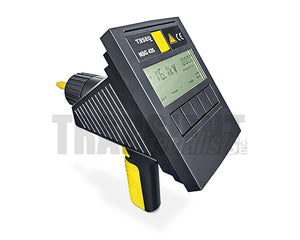
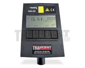
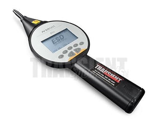
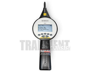
Verification of voltage levels of a simulator can be done through a few different method, however is commonly done through either a voltmeter or voltage divider. Common voltage verification devices include:
The video on the left shows how the ESDEMC ES105 is used to verify voltage levels with the Haefely ONYX16 ESD simulator.
Current Waveform/Pulse
To verify the current waveform of ESD pulses is commonly done during calibration process, which are conducted on an annual basis. This can also be an internal requirement done on a regular basis to ensure the operation of the equipment.

When capturing current waveforms the surrounding environments noise has the potential to impact results. Should the oscilloscope be triggered without a pulse it will be necessary to either move the test area or use a shielded chamber to limit noise. Typical required equipment include:
- ESD Target & Adapter
- 20 dB attenuator
- Oscilloscope with >1 GHz
- Plane for Target to be Mounted
Common ESD Standards
ESD Component Level Requirements
Electrostatic discharge testing can be broken down into three main categories, human body model (HBM), machine model (MM), and charge device model (CDM). Given the number and vast amount of standards that reference these types of testing the main focus of this discussion will be on the most common commercial EN/IEC 61000-4-2 standard. The below table, from an EDN Network, access 8/2/19 [1] (extracted 8/5 www.edn.com). It provides a basic overview of all three types and provides detailed information on voltages and waveforms.

ESD System Level Requirements

IEC 61000-4-2 states "Contact discharge is the preferred test method. Air discharges shall be used where contact discharge cannot be applied." This standard also places specific requirements on the setup required for testing. Below you will find an example of the setup required.
However, for field testing this method may need to be supplemented with air discharge given the nature and large impact that environmental factors can have.
Contact discharge would rarely occur in a normal environment. Take the example above, a person would likely rarely maintain contact with an electrical equipment while generating energy to desired levels without a discharge.
- EN/IEC 61000-4-2 - International Electrotechnical Commission standard currently most recent version 2008. One of the most commonly used main stream commercial testing standards for electrostatic discharge testing. This standard specifies a variety of criteria including waveform, test setup, voltages, etc. The website for the IEC (https://webstore.iec.ch/publication/4189) states (retrieved 8/12/19) " he object of IEC 61000-4-2:2008 is to establish a common and reproducible basis for evaluating the performance of electrical and electronic equipment when subjected to electrostatic discharges."(2)
Automotive
Electrostatic discharge testing for automotive applications is different from commercial based in a variety of ways. The largest variations stem from voltages, test setups, standards, number of discharges, and resistance/capacitance (RC) networks. The voltages of these applications can be in excess of 25kV and often require several RC networks.
- ISO 10605 - This standard is one of the most common international standards and is referenced often by the manufacture based standards. It also requires testing criteria to 30kV as opposed to the lower voltage requirements of IEC 61000-4-2 and other commercial based standards. Texas Instruments, (http://www.ti.com/lit/an/slva954/slva954.pdf) provides an excellent article comparing these two basis for testing. This standard requires RC Networks:
- 330pF/330Ω
- 150pF/2KΩ
- 330pF/2kΩ
Military
Testing for military based applications and standards are also different from both purely automotive or commercial based requirements. A major consideration for the majority of military requirements, including MIL-STD-461 CS118 is the requirements to very discharge methods current and voltage. This is often done through a voltmeter for voltage, and a target, attenuator, cabling and capable oscilloscope. Each testing can also require different resistance and capacitance requirements, making sure the ability to purchase these networks crucial.
- MIL-STD-883 - This standard is based on a more specific application for microelectronic devices for use within military and aerospace systems. This standard also specifies that ESD simulator current waveform verification be done, however specifies only current be done. It also requires substantially less voltage then other standards, the final or fifth step requiring only 4,000 volts. A major consideration for this standard is that it requires specific waveforms and associated 100pF/1500Ohm resistance capacitance configuration.
ESD Test Setup
What is the ESD Test Setup?
Electrostatic discharge testing requirements, commonly IEC 61000-4-2 for commercial products, includes criteria for the ESD test setup. This post will focus on the setup designed for table top equipment under test (EUT) and best practices for manufacturing the associated environment used for testing. When designing the setup IEC 61000-4-2 should be used a reference following the dimensions and measurements provided.
The video overview for designing an ESD setup table top setup includes:
- Horizonal & Vertical Coupling Planes
- Metal information and sizing
- All wood table design
- Setting up components
- Accessories & stand
ESD Table Top Setup
The most commonly used setup is the ESD table top setup. The image on the left is a generic diagram of the setup provided in the Teseq NSG 435 user manual. While the diagram does not providing exact information, it does provide an overview of the setup and the major components. This setup is designed for EUT that can be placed on the insulating material to conduct testing. Common components of an ESD Table top Setup Include:

- Horizontal Coupling Plane (HCP)
- Insulation placed under EUT
- All wood table
- Bleed off Cabling including resistors
- Ground Reference Plane
What is the ESD Table top test setup?
Floor standing EUT Setup
Equipment under test that is designed, or is too large to be placed on a table is tested using the floor standing EUT test setup. This setup while less common this setup does provide a solution for larger EUT.

- Ground reference plane
- Insulating support/pallet
- Earth wire connection
- Mains connection for EUT
- Earth connection to GRP

ESD Testing FAQ
Resources
EC&M - Electrostatic Discharge: Causes, Effects, and Solutions
Desco - Electrostatic Discharge (ESD) A Person Can Feel
Desco Europe - The impact of relative humidity on ESD
InCompliance - Static Electricity and People
ANSI Webstore - IEEE C63.16
Texas Instruments - ISO 10605 Application Note
1. EDN Newtork - Understanding and comparing the differences in ESD testing
2. IEC Webstore - IEC 61000-4-2 Preview
3. Teseq - ESD Testing with precision and convenience
4. EM Test - By the way - What is EMC?
6. Wikipedia - IEC 61000-4-2
7. Interference Technology - Review of MIL-STD-461 CS118