
 Contact Us


Conducted Immunity Testing
Conducted immunity focuses on the impact that noise or interference has when transmitted via physical contact from the culprit to the victim circuit. The goal of the immunity testing is to evaluate the potential impact that the associated interference has on the function of the associated equipment under test (EUT). Testing is done for product reliability and certification purposes which can be required before the product can be brought to market.
These series of tests can vary by application as well as regulatory and manufacturer requirements, however will typically involve:
- Transient Testing
- Conducted RF Testing
- Voltage Dips Testing
- ESD Testing
Conducted Immunity Test Standards
There are many international (generic) and product-specific test standards that exist for system-level EMC testing. The most commonly used and referenced standards in North America and Europe are those from the IEC (International Electrotechnical Commission). This series of standards pertain to Electromagnetic Compatibility (EMC) testing for residential, commercial, and industrial applications(1). The are also specific requirements for both military and avionics testing, which we won't focus on today. Below is a list of a few of the most common IEC immunity requirements and links to the associated page to purchase the standard.
- IEC 61000-4-2 - Electrostatic Discharge
- IEC 61000-4-3 - Radiated EM Field
- IEC 61000-4-4 - Electrical Fast Transients
- IEC 61000-4-5 - Combination Wave Surge
- IEC 61000-4-6 - Conducted RF Disturbances
- IEC 61000-4-11 - Voltage Dips & Interruptions
- IEC 61000-4-12 - Ring Wave Test
The exact standards, requirements, and methods used are determined by the EMC test plan. This guiding document provides an easy to read document providing relevant EMC tests that were conducted, under what conditions, and the results. This documentation can be necessary to manufacturer or import products, as well as for product reliability.
Transient Testing
Electrical transients are caused by a wide range of interference events and have the potential to cause impacts to the operation of electrical systems. These rapid changes in energy can be transmitted device-to-device or at the component level.
There are a variety of different causes of transients, some being internal and some external. It is estimated that between 60-80%(1) of surges, a common transient, are created within a facility as opposed to externally.
Transients are defined by their waveform and aim to replicate the underlying event causing the interference. These pulses can be compromised of voltage and current components and can vary by risetime, duration, oscillation as well as associated level. The can also be broken down into impulse transients and oscillatory transients, with impulse being the most commonly tested.
Electrical Fast Transients (EFT) - IEC 61000-4-4
Electrical fast transient testing, also referred to as burst testing, is one of the most common immunity test that is conducted. These fast rise time, short-duration events, occur in quick succession and are commonly tested on both power and data lines. The most commonly standard for both certification and product reliability is IEC 61000-4-4 which is commonly referenced by more generic standards.
These pulses have a rise time and duration of 5us/50us and are not commonly synchronized when testing AC power. 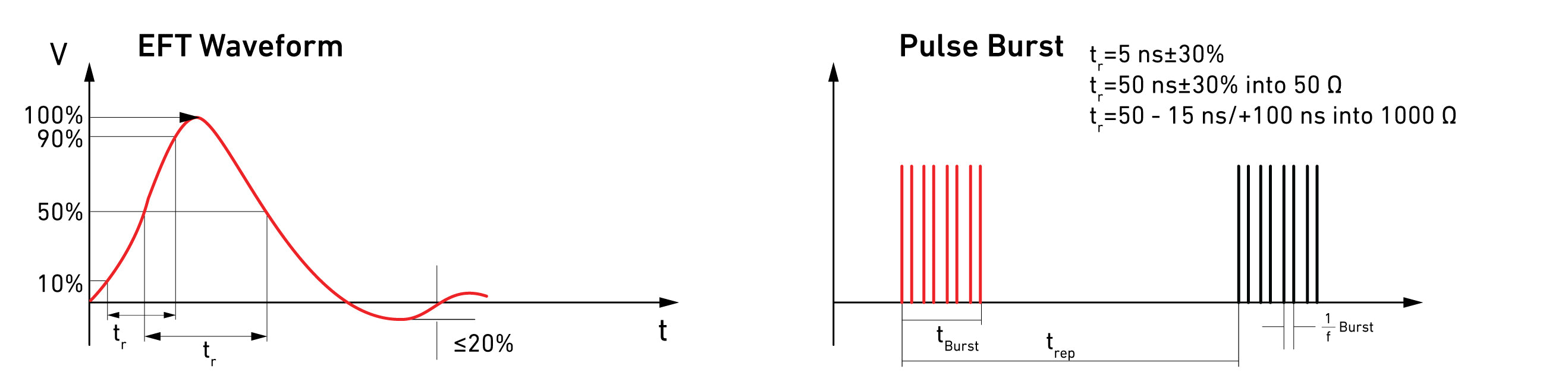
Combination Wave Surges - IEC 61000-4-5
Electrical surges in accordance with IEC 61000-4-5 have both a current and voltage waveform, being commonly referred to as combination wave surges. While both voltage and current surges are also tested individually, it is far less common. For the our discussion we will focus on the most common waveform within the standard, 1.2/50us voltage open-circuit and 8/20us short-circuit.
When discussing surges it is common to hear them described in a rise time and duration format voltage format and associated test level. This is useful when describing IEC 61000-4-5 as this standard includes various voltage waveform including 10us/700us etc.

Conducting Testing

Testing for transients applies the waveforms to the cabling going towards the associated port which testing is being conducted on. This methodology is applied for both power on and power off tests as well as those for power, data, and communication ports. While devices like capacitive coupling clamps are used for testing data lines, coupling decoupling networks or CDNs are commonly used for power line testing.
A variety of criteria can be selected through the associated test generator or associated software including test level, coupling method, etc. It is important to note that all power-on testing must be done through the CDN otherwise damage to the test system will occur! This may require the use of an external power source going into the CDN depending on the EUT/DUT.
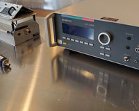
The injection of EFT pulses onto data lines is commonly accomplished through the use of a capacitive coupling clamp. This can done by connecting the clamp to the EFT output on the transient generator and placing the cables in the clamp.

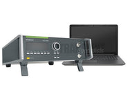
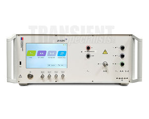
The associated image illustrates a setup using the EM Test NX5 with a CCI capacitive coupling clamp connected used for injecting the electrical fast transients onto the associated data lines towards the EUT. Generally speaking, capacitive clamps are interchange with transient generators so long as the cable has the correct connectors. This offers an easy solution for the majority of data line testing, this cannot be done with combination wave surges which require CDNs.
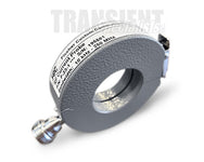
Conducted RF Immunity - IEC 61000-4-6
Conducted RF immunity testing replicates exposure of equipment via the associated cabling to electric or magnetic fields where interference travels down power and data lines towards equipment. These levels of interference which travel down the lines vary in relation to the associated E-Field or H-Field to which the equipment is exposed.
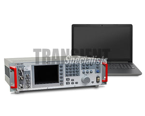
When testing immunity to conducted RF noise or interference there are several injection methods as well as test methods that can be used. The most common, as well as the image shown below is using the substitution method with a coupling decoupling network (CDN) injection device.

Injection Devices
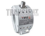
There are three main injection devices used in conducted RF testing, coupling decoupling networks, electromagnetic (EM) clamps, bulk current injection (BCI) probe. Each of the three offers unique benefits, however testing requirements will typically provide guidance on which is appropriate.
IEC 61000-4-6, one of the most common commercial standards, explicitly states a preference for CDNs over other injection devices. CDNs are not only the most effective injection method, but given their design limit the variability of level injection the associated cabling.
It important to keep in mind with the associated device that the corresponding calibration fixture will be needed. In the case of IEC 61000-4-6 50Ohm to 150Ohm adapters will also be required during the calibration. How they're utilized during the calibration process can be seen in the associated video.
RF Immunity Testing
Conducted RF immunity testing using the substitution method as per IEC 61000-4-6 includes first calibrating the associated test system allowing for the system and software to set associated factors for a given test level. When this process has been completed, the calibration factors are removed and associated cables placed through the CDN for testing to begin.

Voltage Dips, Interruptions, & Variations - IEC 61000-4-11
Voltage dips are a result of faults in the local network, largely caused by short circuits. These events can be somewhat common and ensuring that products are not impacted by them is commonly done during immunity testing according to IEC 61000-4-11.
This standard places requirements on the number of cycles with the associated percentage reduction in voltage as well as rise/fall times. These levels are commonly 40%, 70%, and 80% of the nominal voltage. The images below demonstrate potential voltage dips on an AC sine wave.

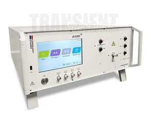
Dips Testing
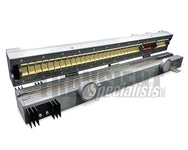
Dips testing typically involves external equipment separate from transient generators, usually variacs or a switch to meet the requirements of the standard. This switch is typically controlled via the transient generator and typically must be designed for that particular model of generator.
The associated video with the EM Test NX5 transient generator and NX 1-260-16 motor variac provides information on the setup and selecting testing criteria for compliant testing.
The variac used in the video is a single phase solution designed for IEC 61000-4-11 testing up to 16 Amps. There are also additional requirements for equipment up to 75 Amps per phase (commonly three phase) including IEC 61000-4-34.
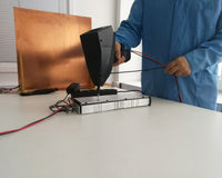
Electrostatic Discharge Testing - IEC 61000-4-2

Electrostatic Discharge, commonly called ESD, we included with this grouping of immunity tests. Electrostatic discharge can be thought of as the rapid release of energy between two differently charged objects caused by the buildup of static electricity. This type of testing is done at both component level and system level, with varying different requirements for each.
ESD testing is defined by the voltage test level and current waveform as well as the resistance capacitance requirements. This is commonly 150pF/300Ohms as required by IEC 61000-4-2 one of the most commercial system level standards.
A series of pulses are applied to the EUT or DUT at regular intervals using either the air discharge or contact discharge method. These is achieved through different tips that can be attached to the front of the ESD simulator, which provides the discharge.
ESD Test Levels and Waveforms

ESD pulses include both current and voltage components, with current waveform criteria (rise time, duration, etc.) verified for compliance to a particular standard.
The image on the left shows the correlation between different test levels and the associated voltages and current up to 8 kV or test level 4.
ESD Current Waveform

The current waveform for ESD testing is a major component in compliance to standards or test requirements. The most common of the commercial standards, IEC 61000-4-2, indicates a .8 ns rise time and current requirements at 60 ns and 30 ns for contact discharge.
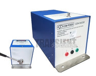
The associated image on the right shows a pulse from the Teseq NSG 435, which is provided by the user manual. This example pulse indicates the common requirements for rise time as well as current requirements at different intervals. Each application or standard has the potential to have different pulse requirements making it crucial to verify capabilities prior to beginning testing.
Conducted Immunity Test Setup
The test setup for immunity testing will vary based on the underlying test as well as the size of the equipment under test (EUT). For floor-standing equipment, equipment too large, or equipment unable to be placed on a table, there is a slightly modified setup to that of smaller equipment. It is important to verify the setup requirements in the underlying standard (including auxiliary equipment and cables) prior to conducting testing.
There are common components used in the majority of the setups used for immunity testing, these will include a ground reference plane, insulating support, and grounding cable connected to the plane. Some standards place preference on the type of metal used, however copper and aluminum are common.
Table Top Equipment
This is the most common setup and the size of the equipment will determine how large the metal plane which the EUT sits will be. Some standards have minimum requirements, however the largest physical dimension will determine the size of the sheet.
Electrostatic discharge testing is one of the most common tests and many of the components in the setup can also be used for transient testing. The diagram below from the Teseq NSG 435 user manual provides a brief overview of the setup and the common components.

- Horizontal Coupling Plane (HCP)
- Insulation placed under EUT
- All wood table
- Bleed off Cabling including resistors
- Ground Reference Plane

Immunity Testing FAQ
References/Additional Information
1)What Are Surges | NEMA Surge protection Institute. (n.d.). Retrieved September 7, 2022, from https://www.nemasurge.org/history/
(1)https://webstore.ansi.org/standards/iec/iec61000electromagnetic