
 Contact Us


Overview
The LV124 standard is a series of quality and reliability tests for 12 volt electric systems established by German automotive manufacturers in 2013. We will be focusing on both LV124 with a fair amount of information from VW80000 as well.
VW80000 is broken down into two sections:
- Part 1 - Electrical tests and requirements on 12 volt electric systems
- Part 2 - Environmental tests and requirements
The different categories of testing (electrical, mechanical, etc.) can be seen with the letter indicated in front of the associated test. Our focus will be on the electrical requirements indicated with an "E", focusing heavily on pulses E-01 to E-15.
Electrical Tests
The tests in Part 1 of VW80000 pertain to 12 volt electrical systems and include E-01 to E-23 tests, which we will focus primarily on pulses E-01 to E-15. The general requirements for these tests are presented in section 5 where test voltages, functional classes, and operating voltage ranges are defined.
The statuses used to define any impacts of testing begin with status A and extend all the way to status E, with E being the most severe degradation of function. Different standards will define these differently an in-depth analysis of 124 vs 148 can be found by clicking here.
VW80000 provides 6 functional classes, the most crucial to vehicle operation being class one while diagnostics and communication being class six.

Test Selection
How power is supplied to the component determines the proper test selection, with some tests being applied to all components.

Test Equipment
The test equipment that is required for pulses E-01 to E-15 would include a programmable battery simulator/source, waveform generator, and a fast switch able to meet test E-10 and E-13 interruption rise time and fall time requirements. EM Test and Teseq (Ametek CTS) provides a variety of automotive equipment that can meet the test requirements of LV124 as well as VW80000, we will be referencing EM Test equipment extensively.
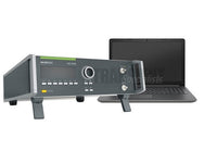
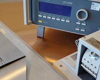
The associated video walks through how the EM Test VDS 200Q100.2 with the AutoWave is used to conduct testing to many of the pulses. The video includes:
- EM Test VDS200Q100.2 & AutoWave Overview
- Required Equipment for LV124 Pulses
- AutoWave.control Software & Configuration
- Conducting LV124 using AutoWave.control Software
Required Equipment
The associated table provides information on which equipment is required to meet each pulse of LV124 2013. Typically, the EM Test AutoWave is mounted in the VDS 200Q series of battery simulators allowing for a single unit solution for the majority of the required waveforms.
Battery Simulators
The battery simulator or DC voltage source is an integral component for all of the LV124 and VW80000 tests with the exception of interruptions tests where the fast switch (EM Test PFM 200N100 in our case) is used. Depending upon the test plan and if pulse E-15 is required will determine if a supply with four-quadrant operation that can quickly move from positive to negative will be needed.
The DC sources commonly used can provide voltages up to 80V with a maximum current rating of up to 200 Amps continuous. Some of these types of sources are designed as "smart" supplies allowing for some of the pulses to be run with no additional equipment.
Some test systems allow for integration of external supplies or sources, in the associated video this is done using EM Test equipment. In the video the EM Test AutoWave and PFM 200N100 are used with the Teseq PA 5840 series of battery simulators. This is done in accordance with the application LV124, allowing for control of the system using the AutoWave.control software.
Commonly, test simulators will vary by the maximum negative and positive voltage, maximum current, number of quadrants, as well as other parameters. Regardless of the caliber of the source, source and synch functionality will be required if more complete coverage of LV124 tests is needed.
Fast Switch & Calibration Adapters
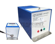
A fast programmable switch is required for both supply and data/communication lines is required for E-10 and E-13 tests. The EM Test PFM200N100 is an ideal solution allowing for dropout or dips testing to be conducted on power lines as well as up to 16 communication lines simultaneously or individually. This equipment can be configured for up to 200 Amps and allows for data/signal lines up to 2 Amps.
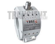
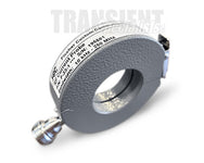
The associated interruptions/dips tests in the standard require a reference measurement or verification. This is done for both E-10 and E-13, with the resistive loads being required to verify slew rates of the waveforms. The associated image illustrates the shows the EM Test CA LV 124 kit and the connection of the kit to the EM Test PFM200N100 for reference measurements. The CA LV 124 kit includes:
- CA LV124-P1R - 1 Ohm for Battery Lines
- CA LV124-P100R - 100 Ohms for Battery Lines
- CA LV124-D1R - 1 Ohm for Signal/Data Lines
- CA LV124-D1000R - 1,000 Ohms for Signal/Data Lines
E-11 Cranking
Cranking tests in LV124 replicates the short duration battery voltage drop and slight rise common with engine starting. The goal of this test is to evaluate the impact that starting engine voltage sags have on the operation of the component. The standard provides different waveform requirements for both hot and cold start situations.
It includes four different tests:
- Cold Cranking (Normal)
- Cold Cranking (Severe)
- Warm Cranking (Short)
- Warm Cranking (Long)
The two waveforms below are for both Test Case 1 - Cold Start and Test Case 2 - Hot Start. These waveforms while not relatively fast, all criteria is in the milliseconds, they are fairly complex. It may be necessary in both cases to have an waveform generator to assist in meeting some of the criteria.

E-10 & E-13 Interruptions
E-10 and E-13 tests both being interruption tests have a series of fast rise and fall times dips to open. The E-10 test case represents interruption in supply voltages (two cases) and E-13 is applied to signal or data lines as well as T.31 return lines. These scenarios replicate contact issues as well as bouncing relays.
Both interruptions tests can have short dropouts of different durations given the potential for a partial or complete disconnection.

E-10 Short Interruptions

This test designed for supply voltage interruptions provides two test cases which involve two switches represented in the associated block diagram as S1 and S2 respectively. Test Case 1 has S1 switched, with S2 statically open and Test Case 2 S1 again switched with S2 negated to S1.
Switch S1 interrupts the power supply to the DUT. Depending on the test case, switch S2, including the required <100MOhm load is active.
E-13 Pin Interruption

The E-13 interruption test doesn't need to be applied to supply pins with the exception of wake-up lines. The test is designed for data and communication lines as well as ground pins. The goal is to replicate the interruption of signal and data individual pins.
One reference measurement each with 100 Ω (±5%) and 1 Ω (±5%) as a DUT substitute must be performed and documented. Verification of the edge steepness must be provided with this test setup. Low-inductance parts must be used as resistors.
Equipment Requirements
These tests both have a series of fast fall and rise times with the voltage dropping out to a lower level. This can be achieved using a fast switch like the EM Test PFM200N100 and waveform generator as described in the chart above.
E-15 Reverse Voltage/Polarity
The E-15 test relates to a situation where the battery is connected in reverse polarity while jumped. The incorrect connection can happen for a variety of reasons (maintenance etc.) regardless of different connectors or terminals sizes. This situation has the potential to occur several times while attempting to jump-start a vehicle and is reflected in the number of cycles of test case 2.
This test is applied to all the components in the vehicle that can be subjected to this type of occurrence. When the reverse polarity test is applied no safety related functions must be triggered.
E-15 consists of two different test cases:
- Test Case 1: Static Reverse Polarity
- Test Case 2: Dynamic Reverse Polarity
Both of these E-15 test case waveforms have rise time (tr) and fall time (tf) of less than or equal to 10ms, which isn't exceptionally fast for automotive transients. These waveforms do however have unique voltage minimums and maximums which span from either 0 or positive voltage to negative.

Equipment Requirements

In Test Case 2 the change in voltage from a positive value to a negative value requires a power source or battery simulator that is capable making the rapid decrease below zero and rapid increase back to Vmax. The associated image shows this decrease from 10.8V to -4V which requires a rise and fall time of less than or equal to 10us.
As the above reference diagram indicates the EM Test solution would be with a VDS 200Q series of DC voltage sources. This also has the potential to be accomplished with a switch with the generator providing Vmax and the subsequent Vmin.
References/Resources
1)ESPEC. (n.d.). Introduction to LV 124 Compliant Products & Services. Retrieved February 3, 2023, from https://www.espec.co.jp/english/products/catalog/lv124.pdf
2) Horacek, T. (n.d.). Technical Note 0105 Dropout Testing. Ametek CTS. Retrieved February 3, 2023, from https://www.ametek-cts.com/-/media/ametekcts/documents/applicationnotes/tn0105_dropout-testing.pdf?la=en&revision=84e29e1c-69e4-43bf-afd8-11043f342fb3&hash=DA47ABE241050DE888E800FAD2A4A7EC
3)Protecting Vehicle Electronics from Reverse-Battery Connection. (2021, October 1). Diodes. https://www.diodes.com/design/support/technical-articles/protecting-vehicle-electronics-from-reverse-battery-connection/
4)User’s Guide PFM 200N100.1 PFM 200N200. (2020, November). Ametek CTS, from https://cdn2.shopify.com/s/files/1/1826/1151/files/User_Manual_PFM_200N100.1.pdf?8442
5)VW 80000 Issue 2017-10 - "Electric and Electronic Components in Motor Vehicles up to 3.5 t".
6)WKS-Informatik. (n.d.). LV124 VS LV 148. Wks-informatik. Retrieved February 3, 2023, from https://www.wks-informatik.de/wp-content/uploads/DocumentDownloads/June2017/LV124_LV148_WKSInformatikSolutions.pdf